Setting Up of CRS
Teacher: Atul Thakur
About the Module The Unit on radio waves and spectrum will be important for you to get an analytical understanding of the underlying technology of radio. While you may not get an opportunity to put this knowledge to use on a day-to-day basis, you will find this useful in understanding radio at a fundamental level.
The last Unit is related to power backup and voltage stabilisation. As noted above, this is a problem which occurs frequently in most rural community radio stations. Choosing the right power back up or voltage stabilisation solution can be a complex task and requires a sound knowledge of how back up and stabilisation can be configured in the context of underlying principles as well as available resources at your disposal.
Duration of the Course: 2 Weeks
Module Introduction
CCRT Module 2 Introduction
The components of a CR station are meant for you to understand the basic building blocks of what constitutes a radio station. However, some of the components are explored in-depth in the later modules.
The Unit on radio waves and spectrum will be important for you to get an analytical understanding of the underlying technology of radio. While you may not get an opportunity to put this knowledge to use on a day-to-day basis, you will find this useful in understanding radio at a fundamental level. Remember that competent technicians don’t just solve problems, but they know why those problems occur as well!
Module Objectives
- Familiarity with processes and principles involved in setting up a community radio station
- Understanding of the technology behind radio waves and electromagnetic spectrum
- Familiarity with solutions related to power back up and stabilisation of voltage
Units in this module
- Components of a CR Station
- Radio Waves and Spectrum
- Basics of Electricity
- Power Backup and Voltage Stabilisation
Introduction
By now, you have already received a broad grounding in the philosophy of community radio, as well as an understanding of the essential decision points according to which we select equipment and technology for a CR station.
This Unit will now discuss the various components of a CRS station, and will provide an overview of how these components are related to each other. It will discuss the key points we need to keep in mind while deciding on a site for the CRS; as well as when we setup the studio and production spaces. Through these discussions, this unit will provide a broad introduction to the CRS as a whole, details of which you will study in further units. You may require approximately 40 hours to complete this unit.
The CR Station
Having understood the philosophy of community radio and the criteria for selection of equipment, it is now time to understand the first steps in actually setting up a CRS i.e. finding a relevant location, and dividing the available space into studio and working spaces.
Site selection
One of the most important decisions we have to take for the setting up of a CRS, from a social purpose point of view as well as a technological point of view, is where to locate it. This process is called site selection, or siting, and is based on a number of critical considerations. Let us look at some of the criteria we need to keep in mind:
The physical location and distribution of the served community
The core of a community radio station is its listener community, by which we mean the core group of listeners whose information needs the station will serve, and for whom it will provide a platform for expression. Given this, it is important that the station should be in a place where these community members can access it easily, and participate regularly in programme creation. In short, the station should be accessible to every member of the local community, young or old, man or woman, physically sound or differently abled. This is why the Community Radio Guidelines (2006), which lay out the regulations governing CR in India, also make it mandatory to establish the CRS within the geographical area where its potential listener community resides.
We can achieve this by first mapping where the potential listeners of the CRS stay, work and live. Once we have a clear picture of this, we must try to locate the CRS as centrally within this area as possible, so that it is roughly equidistant for all the people who live around it.
Simultaneously, we must also try to situate it in a building or space that is already familiar to the community members, and which they are likely to pass during their daily routine: near the village panchayat, say, or a community centre (if there is one). Some CR stations are set up near key crossroads within the locality, or near market places. Note that this can be a challenge where community residential spaces are clustered by caste or profession: Many Indian villages are divided into caste- based and ethnicity- based sectors. It is best to place the CRS in a neutral space, where everyone can be encouraged to participate without hesitation. In keeping with our philosophy of community ownership, the station should be housed in a community donated or provided building. This way, it will become an intrinsic part of the community’s life from the outset. It will also avoid the nuisance value – not to mention financial burden - of paying rent, and being subject to the whims and fancies of a landlord. This is especially important from the point of view of transmission licensing, which locks down your transmitter location to a given physical location for the duration of the license.
Local geography and terrain
The second most important criterion to keep in mind is the physical layout of the land: Whether it is totally flat, undulating, or whether it has a slope or a depression anywhere.
This is important because the propagation of FM, the radio transmission technology used for community radio broadcasting, is line of sight. This means the transmission can only be heard when the radio receiver set can electronically ‘see’ the transmission antenna, with no or few obstacles. This means we must choose a location for the station (and by extension, the antenna and the mast/tower it is mounted on) which is not surrounded by tall buildings, or hidden by a hill or mountain - or situated inside a depression in the local landscape. Such obstacles will block the signal and result in no-reception (“shadow”) zones within the transmission area.
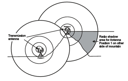
Figure 5.1: Radio shadow zone caused by a mountain situated near the CRS.
Source: CR:A User’s Guide to the Technology, N.Ramakrishnan/UNESCO, 2008
Of course, this does not mean that we cannot use this phenomenon to our advantage on occasion: CR stations, by design and purpose, are low-output-power stations, meant to reach comparatively small areas. But if our community happens to reside in a hilly or mountainous area, setting the CRS on the slope, or at the tallest accessible point in the area may well give it additional range. Just as standing on a hill gives you a vantage point for a commanding view of the surrounding area, such a site could increase your effective range, and reach a larger audience. Such considerations must not, of course, over-ride our primary consideration of accessibility and community participation – so don’t go locating the CRS at a place only a mountaineer or rock climber could access! Moreover, mounting the antenna at a height greater than 30M from the average terrain of the geographical community may pose problems in getting the technical clearance from the authorities.
Local noise levels and Transmission signal strength
Local noise levels
Even while we try to locate the CRS in an accessible place, as close to community life as possible, we have to try and keep ambient noise levels low. By ‘ambient noise’, we mean the general noise levels in the area. Good recording quality is dependent on having minimum background sound, unless we are trying to create a feel of the area and context. If the ambient noise levels are high, we will have to invest more effort and resources in blocking the external sound from reaching the studio. (This is called “sound proofing” the studio.) On the other hand, if we can find a site that is accessible but where the ambient noise levels are low, we will need to do comparatively little to make the studio spaces suitable for recording audio.
Transmission signal strength
Transmission signal strength is a measure of how powerful the Effective Radiated Power (ERP) of the transmission system is. Just as a brighter bulb illuminates a larger area, a transmission system of higher output power can reach a larger area with the signal it transmits. Another factor that affects the signal strength is the effective height of the antenna above the average terrain (EHAAT). At a purely theoretical level, some areas could benefit by an increase in EHAAT, which could overcome physical barriers or geographical factors to some extent.
At a practical level, though, the transmission strength for a CRS is limited to 100 Watts of Effective Radiated Power (ERP) by the Community Radio Guidelines (2006) issued by the Govt of India. So we cannot increase the strength of our signal output in order to reach a greater area. However, the policy guidelines do allow for increase in ERP of up to 250 Watts in special cases such as if the community is sparsely distributed in the region surrounding the proposed site; there are challenges related to broadcasting in hilly or heavily obstructed terrain. In case these conditions exist, it is possible that the station could be allowed a higher transmission output.
The trade off between siting criteria
While it is important to keep the four factors we have discussed above in mind, we must also be realistic in understanding that we will rarely find an ideal site that meets all these requirements at the same time. You will have to trade off all these factors against each other, and take a decision that is in the best interests and purpose of the station. Very often, you will find that the decision is only partly in your hands, since the decision may eventually have to be taken on the basis of pure convenience and the availability of adequate space. So keep these criteria in mind to the extent possible when weighing options against each other.
Space Allocation
Now that we have selected a suitable site for our CRS, it is time to examine how we will divide up the space that we have into suitable work spaces. Again, it is wise to remember that CR stations often work with community donated spaces, and often without the resources to put up a building from scratch. So it requires a bit of ingenuity to adapt the ideas in this section into feasible plans.
Broadly, there are three types of spaces that a CR station needs besides the transmission set up:
a. A broadcast studio (often also called the ‘live’ studio)
b. A production studio (often also called a ’recording’ studio)
c. An office and administrative space
Let us look at these three spaces in detail.
The Broadcast studio is the primary studio space for the station. This is where the broadcast is managed from, and where the announcer or programme compere sits during the broadcast to make announcements. It is often referred to as the ‘live’ studio, because the audio from the studio floor can be played out directly over the transmission system.
The Production studio or the recording studio is the space where recordings are done for programmes that will later be edited and finished. The production studio is usually equipped with a sound booth or a recording floor where audio can be recorded in carefully controlled conditions.
The Office space or administrative area is the place where the volunteers and CRS team members can sit and work on production-related or management-related tasks. It is the space where scripts are written, records are maintained, and where visitors can make enquiries.
But, a small or medium CRS setup may actually have space for only one small studio that has to make do as the broadcast and the production studio. This can sometimes pose practical challenges to time management, because programme editing tasks may have to be suspended when the studio goes ‘live’ for broadcast. If broadcast hours for such a stadium are extended, and take up more than six hours a day, this will leave very little time for other editing work, because editing usually takes far more time than a live programme. In such cases, some CR stations dedicate one or more systems in their administrative areas for editing work when they can be spared.
Beyond these three basic spaces, if there is additional space available, the CRS could use it to set up a training hall, or a spare studio, or even a store where the equipment and recording archives can be maintained. Some CR stations develop outdoor spaces where they can conduct meetings, or hold gatherings and functions. Some have even been able to set up small kitchen spaces, so that everyone can have a cup of tea, or cook small meals as they work.
If it is feasible, it may also help to have a small enclosed area separating the entrance to the broadcast studio from the other spaces, so that you pass through two doors in order to enter the studio proper. Such a space is called a sound lock; and it serves to insulate the studio from external noise, specially when a broadcast is in progress. Opening only one door at a time keeps outside noises from filtering in.
In the next section, we will examine some sample layouts for CR station setups and we will discuss some of the special arrangements that we have to make in studios to ensure good audio quality.
Studios for CR Stations
In the previous section, we have discussed some of the common space setups and studio arrangements in a CR station. Let us now look at some possibilities in which the studios partition of CRS can be laid out.
Sample layouts
The Basic one-room CRS
Source: CR:A User’s Guide to the Technology, N.Ramakrishnan/UNESCO, 2008
As you can see from Figure above the basic one room CRS, has single space that serves as the broadcast, recording, storage and work space. This kind of a setup only requires a small area, and very little setup time. On the other hand, with this kind of a setup, it can sometimes be a challenge to do more than pre-recorded or talk based programming, since you may not have space in the studio to record radio drama, or groups of musicians.
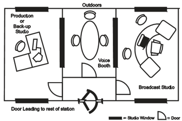
A simple 3 studio CRS
A CRS layout that allows us the kind of space depicted in Fig 5.3 provides for a better distribution of space, and a better distribution of tasks across the spaces. Note that the door at the bottom of the schematic would lead to the remaining spaces of the station, if such spaces are available. If they are not, this may constitute the CRS in its entirety. The voice booth in the centre can be used flexibly to provide a recording floor for both the production studio on the left and the broadcast studio on the right.

Where we have the space and the resources to be able to establish a more well-equipped CRS, we can set up a station that looks like the one shown in Figure above. Note that we can now accommodate a formal office space, as well as a kitchen and a reception where we can seat and meet guests and visitors. Since the production studio is completely separated from the broadcast studio, programme recordings can carry on even during broadcast hours.
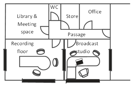
If we change our priorities slightly and dispense with the kitchen space, we can create a library and meeting/training space for the station, as well as a small store for equipment. In the above Figure, we have dispensed with the production studio as well – with recordings done in the broadcast studio when it is free. This may also allow us to have a slightly larger recording floor.
Hence it is important to realize that there is no ‘standard’ way to set up a CRS space and studios. You have to be very clear about how much space is available, and what the priorities are. While these sample layouts are meant to bring out some of the decisions you will take, on the basis of these, priorities may not be implemented as they are shown! Depending on the resources available, you may like to equip a small one room station to start with, then slowly expand the station by setting up more studio spaces, offices and editing rooms. This will allow you to start small, with comparatively less resources; and also to think about the new spaces as you set them up.
Acoustic treatment & Sound-proofing
Ambient noise refers to any background sound that we do not wish to have in our recording. We have already discussed the need to keep ambient noise as low as possible when selecting a station site; but this alone will not guarantee a complete absence of ambient noise. There may be other people working at the station, and there may still be the occasional noisy vehicle passing by outside, which may cause noise that ends up in the recording.
Echo and reverberation, on the other hand, are caused by sound reflecting off the walls and floor of an enclosed space: The reflected sound reaches your ears a fraction of a second after the original, making it sound a little extended, and giving it the ‘hollowness’ that we associate with empty rooms. (This is especially noticeable in smaller rooms – bathrooms, for instance, since the tiled walls of a bathroom provide hard surfaces that reflect the sound even more. Try singing in the bathroom and see how different it is from when you sing the same song outdoors.)
If the difference between the original sound and the reflected sound is too short for you to perceive them as separate sounds, we call the effect reverberation (orreverb, for short). If, on the other hand, the sounds are perceived distinctly, we call it an echo.
As human beings, we can learn to ignore unwanted sounds and focus on what we want to hear: In a noisy gathering, where a large number of people are talking at the same time, you can still focus on what one of those people are saying. Microphones, on the other hand, are machines, that cannot make this distinction. Thus, if we record in a space that has high ambient noise or reverb, what you get is an indistinct (‘muddy’) recording that does not sound clear at all, and which is difficult to edit. It should be clear, then, that if we are to record sound ‘cleanly’ – that is, we would like the sound to be recorded as faithfully as possible, and with as little unwanted sound and reverb as possible, we must make some special arrangements within the studio spaces to minimize the impact of both.
Sound proofing
The easier of the two to address, in some ways, is the ambient noise. We have to find an effective way to block external sounds from coming into the studio. We do this with a variety of different techniques. This can be more easily done in rural areas and sparsely populated areas when compared to urban and densely populated areas.
To start with, the studio spaces should be housed in a building with thick load bearing exterior walls – 9” or more if possible. The masonry itself acts as an effective insulation against sound transmission. It also helps to have a free standing building, because there is a greater chance of sound filtering through the walls in a wall-to-wall construction, where adjoining buildings share walls.
We can also set up a set of double doors at the studio entrance, so that people entering the studio have to open the first door, close it, and then open the second door to come in. The space between the two doors then acts as an additional layer of insulation, and is called a sound lock. The doors themselves can be made of layers of plywood in a wooden frame, with glasswool or thermocol sheets sandwiched between the outer layers. This makes the door thick and sound-absorbing, but light. Rubber gasketing around the edges creates a air-tight and sound-proof seal for the doors, so that sound doesn’t enter through any cracks. A glass porthole fitted in the studio doors at eye level allows people to peer in, so that they do not interrupt a running broadcast or recording.
Lastly, all windows in the studio area opening on the exterior – and it is a good idea to have them, since this will allow natural light to come in – should be double glazed. This means the windows should have not one, but two panes of glass, each set in a rubber or silicone gasket. Each of the glass panes should ideally be at least 5 mm thick, with a separating air space of 5-8 cm between them. The two panes should be angled slightly towards each other, so that they don’t set up any internal reflection of sound between them, causing the panes to buzz.
It is important to remember that sounds enter through the smallest gaps. So ensure that there are no unnoticed cracks or gaps in the studio walls, or any hidden ventilators. Any ducts or pipes passing through the space should be well grouted – that is, the gaps around it should be filled with cement or plaster of paris (POP), so that the gaps are closed.
The large window between the control room - the space where the recording is made - and the studio floor itself also needs some special attention. This is an important window, since the person doing the recording (in the control room) and the artistes or guests in the studio communicate through this window. We follow the same principle as what we saw for the exterior windows to create a double panel window with angled panes. Remember to put in some silica gel between the panes to prevent moisture from condensing between the panes, where it would be difficult to clean.
Acoustic treatment
Now it is time to pay attention to the techniques and materials which we will use to cut down (or “dampen”) reverberation in the studio space. Some of this will be achieved by the angled window panes themselves, which will cut down sound reflection from the window spaces.
A professional grade studio uses a wooden frame over each wall, fitted with large fibreboard or corkboard tiles. The tiles are fitted over packed layers of glasswool, and each tile has variably sized holes drilled through it. Once fitted, the holes let the sound pass through, where the glasswool dampens it, and absorbs it. Other studios use angled wooden sections fitted to the walls to reflect the sound unevenly. Floors and ceilings may be mounted on absorbent materials like cork, or cushioned by spring systems or rubber runner. All these techniques are quite expensive, and are usually charged by the installers on a ‘per square foot area’ basis.
Community radio station budgets calls for use of local materials in an intelligent way, so that we can achieve the same purpose with less expense. Note that this does not mean compromising on the quality of acoustic treatment, or the resulting audio quality.
One way to start is to establish the studio area in a space where the walls do not exactly parallel each other on all sides: Parallel walls create maximum reflections. Walls that have insets and bends can often help reduce the problem to a great extent.
A simple way to cut reverb down sharply is to attach materials to the wall and break up the hard surface. The low cost and easy way to do this is to use cardboard egg trays – the kind used by grocery shops to store eggs. Use a strong glue to paste these trays on the vertical walls and ceiling in even rows, so that the indented surfaces point inwards facing the studio. The soft papier-mâché material of the tray, along with the uneven surface give a striking reduction in audio reflection from the walls. Remember to treat the trays with a strong insecticide before you paste them on to the walls.
Figure 5.9: Egg tray covered walls in Gurgaon Ki Awaaz CRS, Gurgaon
Photo courtesy N.Ramakrishnan/Ideosync
Some studios have successfully used sheets of cane matting hung from the ceiling in front of each wall. Others have used thick curtains on rails all around the studio space - the folds in the curtains and the materials absorb and deflect sound and the curtains can be opened selectively to reveal sections of the reflective wall in order to change the audio characteristics of the space.
Other Considerations
Dust-proofing the studio
One of the greatest challenges of working with technical equipment, especially the electronic ones in tropical countries, is the climatic and environmental conditions that the equipment has to face. And of all these conditions, the biggest enemy of equipment is dirt and dust – so much so, that a large proportion of breakdowns and maintenance issues happens simply because we do not have procedures in place to prevent dust collection.
Since the studio spaces are expected to be used by multiple individuals and members of the community, the only realistic way to keep the spaces dust -free is to encourage a sense of belonging and ownership of the space by everyone, so that keeping it neat like one’s home becomes second-nature for everyone. Shoes should be left outside the main entrance – a shoe rack and a signboard there are good ideas. The rubber gaskets we discussed in, can also play a dual role: they can provide a seal that prevents dust from entering the studio, if everyone can follow the simple procedure of keeping the doors closed at all times.
Many spaces that are used by CR stations are not originally designed for use as studios and broadcast stations. As a result, they often have inconvenient windows and doors that provide multiple entry points for dust and dirt. If you are faced with this situation, replan your layout so that you minimize entry points into rooms and studios. Windows and doorways can be bricked up, or sealed with double paned glass in order to preserve the natural light. Make the station spaces as easy to clean as possible – leave as few nooks and crannies where dust can gather as possible.
Air conditioning: Should we or shouldn’t we?
To start with, let us be clear that air conditioning a CRS is not mandatory. It may not even be necessary. If your station is housed in an old traditional building with high ceiling, or one with floors above, or in the hills or by the sea, it may already be cool enough.
However, if your station is set in a building with an exposed terrace, or in a place with a really hot climate, air conditioning may become necessary. This may be compounded by our attempts to keep dust out, as this may mean we may have blocked several natural vents for the circulation of air. Some equipment can also heat up a lot in use – transmitters, for instance, or poorly ventilated computers.
If air conditioning is necessary, the best kind are split AC units, where there is an internal blower unit, and an external compressor unit, with pipes connecting the two. These are better, because the compressor unit is noisy, and by keeping it out of the studio, we are avoiding unnecessary ambient noise. A window AC would not do, since exterior noise would come through the AC’s internal mechanism into the studio. Ducted systems that cover the whole station space would be best, but are often too expensive for CR stations.
When installing a split AC within a studio, ensure that the hole in the wall where the piping and tubes go through is properly grouted and sealed. Also ensure that the compressor unit outside is installed with sufficient space around it, and off the ground. Remember that in humid conditions, water can drip from the interior unit. There should be a drainpipe leading out of the unit which is also directed outside the studio along with the other piping.
In conclusion, it may feel good to have cool air within the studio, but AC units come with their own downsides:
1. They consume a lot of power, which can mean large recurring power bills for the station. It also means that if your station is in a power poor area, the investment may not be worth it.
2. They require regular maintenance to run at peak efficiency, which means an additional task for the CRS team – not to mention servicing and maintenance costs.
Estimating the station’s AC requirements
The cooling capacity of ACs are rated in BTUs (British Thermal Units) or more usually in tons (1 ton = 12000 BTU per hour). The ton measure refers to the volume of air that can efficiently be cooled by the AC, and 1 ton, 1.5 ton and 2 ton ACs are most common.
Divide the cubic feet volume of your room by 600 to arrive at the basic tonnage capacity required.
Add 0.5 tonnes for every 10 people occupying the room at the same
time.
Similarly add 0.5 tonnes for every 1500 watts of appliances or lighting present in the room (A computer would consume about 300 watts and a regular bulb, 40 to 60 watts).
Calculate the volume of your space on a similar basis for a rough estimate of the AC capacity that you need.
Selecting appropriate studio furniture
Installing studio equipment means, of course, that we also need to have some furniture to place our equipment on. Once again, the key concepts to remember are: hard wearing, and modular. Essentially, a CRS needs furniture which can withstand heavy use, and which we can re-order into a different pattern as per our requirements. It would also be best to have a reasonable idea of what equipment you are going to buy before finalizing the furniture, so that we can be sure that the dimensions are correct. Depending on what is more convenient, furniture can be ready-made, or made to order by a carpenter.
Office furniture is probably the easiest to set up and arrange. Plan for a couple of working desks, a few computer tables, and storage units for files, papers and stationery.
Studio furniture needs some special attention in terms of design. The traditional professional studio configuration is to have a half-moon shaped or U-shaped desk, in the middle of which the compere or recordist sits. The idea is to have all parts of the table within easy arm’s reach, so that the compere can simultaneously attend to multiple devices as he or she speaks into the microphone. But given our purpose, and the low- cost philosophy, almost any furniture configuration can be put to good use.
Keep in mind that:
- Even desks carrying various pieces of equipment should allow you at least some working space which you can use to hold notes or write on. If the desk is so covered with equipment that you cannot move for fear of knocking something off, it is hardly a practical arrangement.
- Studio chairs should be sturdy, and must not squeak or groan when sat upon. Most importantly, they should be comfortable to sit on for extended periods of time – so get the best chairs you can.
- In the control room, the furniture should be set up in such a way that the recordist can easily look through the window onto the studio floor without straining or getting up.
The studio floor itself can be kept as bare as possible, to allow it to be used flexibly, But a small round table with a couple of chairs is not a bad idea, as it will allow you to conduct interviews there. If you expect your studio floor to regularly be used for panel discussions though, by all means feel free to get a larger table that can seat four or five people.
Studios should also have plenty of shelf space for storage. You can never have enough storage! Shelves should preferably be closed, and must accommodate manuals, cables, accessories, and small ancillary equipment. Expensive items, especially those that are issued to team members on request, should be stored in locked cupboards for safety purposes.
Many modern studio equipment also come in ready to -fit standard slotted racks. These racks are generally made to standard sizes in multiples of 44 mm, allowing the stacking of recorders, patch panels and amplifiers, and making space-use more efficient.
Always keep in mind that with imaginative use of furniture, you can easily obtain a far better alternative than buying a great deal of expensive furniture. Good planning, and a sensible carpenter go a long way in terms of making the best use of limited space!
Radio Waves and Spectrum: Introduction
In previous pages, we discussed a range of issues relating to community radio. These issues were about the philosophy guiding the concept of community owned and community managed media; the policies governing the establishment of community radio stations in India; the factors we need to keep in mind while deciding a location for the station; and the various considerations we need to address while designing and setting up a CRS.
It is now time to take a pause and look at a fresh set of basics to sharpen our understanding further: What are radio waves, and where do they come from? How does the process of radio broadcast actually happen? When did it start? In this Unit, you will learn about the science behind radio broadcasting, and the natural phenomenon of electromagnetism. You will also learn about how the usage of radio waves are governed in this country. For studying this Unit, including working on the various Activities, you may need around 40 hours of study.
Learning Outcomes
After working through this section, you will be able to:
- discuss radio waves and their implications for CR.
- explain the broadcasting spectrum for radio.
- describe different frequencies of operation of radio broadcasting.
- analyze issues related to regulation of radio waves, spectrum and frequency.
Electromagnetic Spectrum and Radio Waves
Before we begin to understand what radio broadcasting is all about, and how this process takes place, it is important that we first understand some fundamental facts and measures related to the science behind radio broadcasting. For this, we must go back to some of the basic physical properties of waves, energy and radiation.
Basic characteristics: Amplitude, Frequency and Wavelength
You must all have thrown a pebble into a pool or puddle of water at some point in your lives. What happens? The stone causes a series of ripples that start at the point where the stone hits water, and spreads out in concentric circles or rings from that point outwards. Simply put, the energy which the flying pebble possessed at the moment it hit the water surface, has been converted into the up and down movement (‘oscillation’) of the water particles, which have now formed WAVES. Hope you can now able to visualise the concept of waves. Here, you can watch a small video, which will help you to understand the concept of waves more clearly. Please visit at http://tinyurl.com/p5kykyc for the video titled ‘Introduction to Radio Waves’.
So a 'wave' is an up-and-down or side-to-side movement of the particles in a medium. We usually represent waves graphically as given in Figure below.
There are three key qualities of a wave that we must become familiar with. These are:
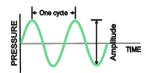
1. Amplitude: This is the difference between the highest (‘peak’) and the lowest portion (‘trough’) of a wave, and is a measure of the strength of the wave. The larger the amplitude, the higher the energy of the wave, and the greater the distance it will travel. In terms of sound waves or audio waves, the larger the amplitude, the louder the sound. The concept of amplitude and frequency is illustrated in Figure below.
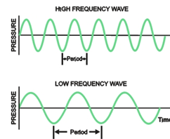
2. Frequency: Frequency refers to the number of waves that pass through a given point in space every second as shown in Figure below.
If you look at the diagram in Figure above, the wave on top has a greater number of cycles within the same distance as compared to the lower wave. Thus, you will see that if we choose any one point on the horizontal line, and imagine both waves moving to the right at the same speed, more cycles of the wave on top will have passed that point after one second than for the lower wave. The upper wave could thus be said to have a ‘higher frequency’ and the lower wave a ‘lower frequency’.
Frequency is measured in Hertz (Hz). One Hertz (1 Hz) corresponds to one cycle crossing a given point in space every second. (By extension, a wave with a frequency of 100 Hz would have a 100 cycles pass that point every second.)
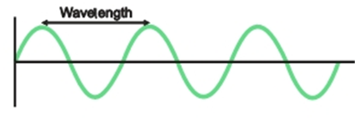
3. Wavelength: Wavelength refers to the distance between two successive waves, as shown in Figure below.
This distance can be measured as the difference between two adjoining peaks, or two adjoining troughs..
Frequency and wavelength have an inverse relationship, which means the greater the frequency of a wave, the shorter the wavelength; and vice-versa.
Radiant energy and Electromagnetic Spectrum
Have you ever stood in the sunlight and felt its warmth on your skin and face? But the Sun is a ball of hot gas millions of kilometres away from us, across the vast empiness of space. How could its heat reach us across this vast distance and through a vacuum?
The answer is that every object gives off energy in various ways. Objects at a higher temperature give off more energy and objects at a lower temperature give off less. The Sun, being a superhot ball of gas where nuclear reactions are going on continuously, gives off energy in a number of different ways. This ‘giving off’ of energy is called radiation; and the energy so given off is termed radiant energy.
Radiant energy could be in the form of light, or heat, both of which we can immediately sense with our eyes and our skin respectively. Then again, it could be in the form of such waves that we cannot see or hear, or even feel directly with our limited senses, but which can be detected by devices that we build. One example is X-Rays, the invisble rays that are used by medical science to look through skin and flesh to see parts of our skeleton. Together, all these kinds of radiant energy are often called Electromagnetic Wave Radiation, since the energy is actually radiated in the form of waves, and has properties linked to both, electricity and magnetism. (Electricity is the phenomenon of the flow of charged particles from one point to another in a conducting medium, such as a copper wire; and magnetism is the phenomenon whereby some material can attract or repel other objects.)
Waves in water, or sound in air are both examples of waves which need a medium to travel through: water and air, respectively. Electromagnetic wave radiation, on the other hand, can travel across vacuum, without any medium. (They may, however, be impeded or affected by any electric or magnetic material or conductors in their path.)
Unlike water or air, which can move physically - up and down or side to side - when set in motion, electromagnetic wave radiation does not physically move any particles. Rather, an electromagnetic wave may be understood as the change in the levels of electromagnetic charge in a given point in space over a period of time.
All electromagnetic waves travel at the speed of light in a vacuum. The speed of light is a constant 299,792,498 metres per second – which is very fast indeed! For all practical purposes, over short and medium ranges, this is almost instantaneous, which is why even if a bulb is switched on a long distance away, you see it immediately – because the time taken for the light to reach you is so short that you cannot perceive the gap.
Electromagnetic wave radiation is mostly classified on the basis of the frequency of the waves that are radiated. They range from comparatively low frequency waves (in the KiloHertz or thousands of Hertz range) to comparatively high frequency waves (in the GigaHertz – or millions of Hertz – and TeraHertz – or billions of Hertz, or higher range). Together, all the frequencies of electromagnetic waves are called the electromagnetic spectrum.
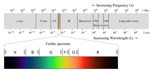
As you can see from Figure ablove,Visible light forms one part of the electromagnetic spectrum which is perceivable by us with our eyes. This portion of the electromagnetic spectrum is, appropriately, called the visible spectrum, and is composed of the familiar colours Violet, Indigo, Blue, Green, Yellow, Orange and Red (known by the acronym VIBGYOR), which we see in a rainbow; or when sunlight is split by a prism. In the visible spectrum, red is at the lower frequency end, and violet at the higher frequency end. Above the blue end of visible light – that is at higher frequencies than blue light – lie Ultraviolet Rays, X-Rays and Gamma Rays. Below the red end – that is, at lower frequencies than red light - lie Infra Red Rays, Micro Waves and Radio Waves.
The Radio Spectrum
Radio waves are those electromagnetic waves that typically fall within the 3 Kilohertz (kHz) and 300 Gigahertz (GHz) range of frequencies.
They can occur naturally – the Sun and other astronomical bodies, as well as lightning are sources of radio waves. Radio waves are used for location beacons, and to generate direction signals for radio location. They are also used for broadcasting, which means producing them by artificial means, so that they can carry an audio signal of our choice to a distant place.
The table below (sourced from Wikipedia) shows the entire gamut of radio frequencies and how they are categorized:
|
DESCRIPTION OF RADIO WAVE BAND |
FREQUENCY RANGE |
|
Extremely Low Frequency (ELF) |
3 Hz/100 mm - 30 Hz/10 mm |
|
Super Low Frequency (SLF) |
30 Hz/10 mm - 300 Hz/1 mm |
|
Ultra Low Frequency (ULF) |
300 Hz/1 Mm - 3 kHz/100 km |
|
Very Low Frequency (VLF) |
3 kHz/100 km - 30 kHz/10 km |
|
Low Frequency (LF) |
30 kHz/10 km - 300 kHz/1 km |
|
Medium Frequency (MF) |
300 kHz/1 km - 3 MHz/100 m |
|
High Frequency (HF) |
3 MHz/100 m - 30 MHz/10 m |
|
Very High Frequency(VHF) |
30 MHz/10 m - 300 MHz/1 m |
|
Ultra High Frequency (UHF) |
300 MHz/1 m - 3 GHz/100 mm |
|
Super High Frequency (SHF) |
3 GHz/100 mm - 30 GHz/10 mm |
|
Extremely High Frequency (EHF) |
30 GHz/10 mm - 300 GHz/1 mm |
|
Tremendously High Frequency (THF) |
300 GHz/1 mm - 3 THz/0.1 m |
Different frequencies of radio waves have different propagation characteristics in the Earth's atmosphere. Longer waves may cover a part of the Earth very consistently through ground wave propagation. Shorter waves can reflect off the ionospheric magnetic layer of the atmosphere, and travel around the world. Much shorter wavelengths bend or reflect very little and travel on a line of sight.
Different parts of the radio spectrum are used for different radio transmission technologies and applications. Radio spectrum is typically government regulated in developed countries and, in some cases, is sold or licensed to operators of private radio transmission systems (for example, cellular telephone operators or broadcast radio and television stations). Ranges of allocated frequencies are often referred to by their provisioned use (for example, ‘cellular spectrum’ or ‘television spectrum’). Some parts of the radio spectrum are unlicensed – for example, the frequencies used for Wireless Fidelity or WiFi internet, or Citizen Band (CB) radio. Cordless telephones also used an unlicensed part of the radio spectrum.
Frequency Bands for Radio Broadcasting
For practical reasons, radio spectrum is subdivided into smaller sections called Bands, which are further subdivided into specific frequencies called channels. Each of the ranges you see in the table above is actually a Band (VHF Band, UHF Band, and so on).
By international convention, certain bands have been reserved for certain kinds of broadcasting, as we have noted previously. In this section, we will understand the primary bands assigned for radio broadcasting globally.
Medium Wave (MW) and Shortwave (SW)
In most countries across the world including India, the band between 535 kHz and 1605 kHz is reserved for Medium Wave radio broadcasting. Medium Wave is often shortened to MW, the letters you see on a radio tuner dial. ‘Medium Waves’ refers to the size or wavelength of the corresponding radio waves, which range from 560 metres to 187 metres. (This means each wave in a medium radio wave is 187 metres or more in length – upto a maximum of more than half a kilometre!)
One of the key characteristics of medium waves is that their principal mode of propagation is through ground and they follow the curvature of the ground well. They can also get reflected from the atmosphere’s ionosphere in night allowing medium-to-long-range broadcasting. Some of the countries of the world are using medium wave transmitters upto 2000 Watts (2 MW) power, covering a range of several hundred kilometres radius. MW transmissions, however, suffer from night time shrinkage of service because of interference from sky wave signal, which is otherwise absent in daytime. All India Radio is making use of the Medium Wave band for its domestic broadcasting and also for service to neighbouring countries with transmitters ranging from 1 KW to 1000 KW.
Shortwave as a medium of radio communication received its name because the wavelengths in this band are shorter than 200 m (1500 kHz) which marked the original upper limit of the medium frequency band first used for radio communications. Short wave is also known as HF ( High Frequency ) that covers the range of 3-30 MHz for radio broadcasting.
Initially thought to be useless, shortwave radio is used for long distance communication by means of reflection from the ionosphere. This mode of propagation is also known as skywave or skip propagation, allowing communication around the curve of the Earth. It is therefore mostly used for international broadcasts by various countries including India. In India, however, Shortwave ( HF) is also used for supplementing its domestic MW services by virtue of special dispensation given to it by being a tropical country.
Medium Wave and Shortwave broadcasting is conducted in Amplitude Modulation ( AM), regarding which you will read more in the section below.
Amplitude Modulation (AM) & Frequency Modulation (FM)
Radio broadcasting can be categorized not only on the basis of the frequency bands that are used, but also by the precise method used for creating the radio signal. Let us understand this in greater detail.
As we have understood in a previous section, radio broadcasting is achieved by combining the source audio (the audio signal) with a radio carrier wave. A signal is any electronic stream that carries information. A carrier wave, as the name suggests, is a high frequency radio wave on which the audio signal can be mounted, or with which, you can say, it can be combined, in order to carry the audio signal much further than it would otherwise go. (Just as having a vehicle can let you travel comfortably over larger distances, the carrier wave carries the audio signal over a greater distance owing to its higher energy and greater capacity to travel over a distance without being dissipated.). The process of combination of the carrier wave with the audio signal is called modulation of the carrier wave.
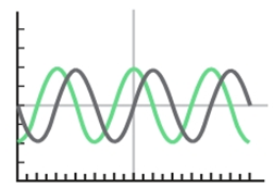
One of the ways in which this can be done is through amplitude modulation or AM. In AM, the modulation of the carrier wave results in the creation of a wave with the frequency characteristics of the radio wave , but whose amplitude varies according to the audio signal.
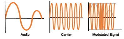
As you can see, the output radio signal continues to have the carrier wave’s frequency, but now has an amplitude variation that resembles the original audio. AM broadcasting continues to be the modulation technology used for MW and SW radio broadcasting.
The key challenge of AM broadcasting is that it is easily disturbed by natural phenomena like lightning, or by the sparkplugs from motor cars; or even high tension electrical cables, which generate strong magnetic fields around themselves.
Frequency Modulation, or FM, was a modulation technology that was developed subsequent to the invention of AM. In the case of FM, the modulated wave continues to have the same amplitude as the original carrier wave, but now has variations in frequency that correspond to the frequencies of the audio signal, as shown in Figure below.
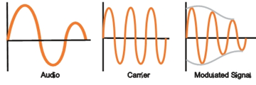
Frequency modulation provides excellent high fidelity audio, and the ability to broadcast stereo audio – discrete signals for the left and right speakers – with comparatively few complications. It is also not disturbed by atmospheric or electrical phenomena, making it well suited to urban broadcasting. The advantages of FM over MW (AM) have already been given in Module-1. It is because of those advantages that it has been chosen for Community Radio. FM broadcasting is primarily a line of sight ( LOS) propagation, although propagation also takes place beyond LOS by means of diffraction, scatter and ducting. However, the summary of various modes is given below :-
|
AMPLITUDE MODULATION ( AM) |
|||
|
Mode MF/MW |
Total Band 300-3000 KHz |
B’casting Band 526.5-1606.5 KHz |
Propagation Ground wave (Day & Night) Sky wave (Night) |
|
HF/SW |
3-30MHz |
3-30 MHz |
Sky wave ( Day & Night) |
|
FREQUENCY MODULATION ( FM) |
|||
|
Mode VHF |
Total Band 30-300 KHz |
B’casting Band 40-230 MHz FM Band 87-108 MHz
|
Propagation Direct wave with ground reflected wave upto L.O.S. Diffraction, Scatter and Ducting beyond L.O.S. |
A Brief History of Radio Broadcasting
The international experience
Radio waves were first predicted by the British physicist James Clerk Maxwell as part of his calculations on the wave theory of electromagnetism in 1865. Maxwell suggested that light and electromagnetism were connected phenomena. The first successful radio transmission was made in 1879 by James Edward Hughes but it was only in 1889 that the German physicist Heinrich Hertz proved conclusively that Hughes’ experiment involved the transmission of electromagnetic (radio) waves. It is after Heinrich Hertz that our measure of frequency, the Hertz, is named.
By 1892, the physicist Nikola Tesla had demonstrated the transmission of energy through radio waves and predicted that it could be used for the transmission of information. This was subsequently demonstrated by the Italian physicist Guglielmo Marconi, who made the first practical radio transmission system capable of transmitting a signal over a range of one to two kilometres. (Though Marconi is widely regarded as the first radio broadcaster, there were a large number of researchers on radio by then, and this status is disputed. Indian scientist J.C.Bose is now co-credited in many publications as the inventor of radio broadcasting.) Marconi would later set up a company to explore the military and commercial possibilities of radio.
Though there are many claimants to the title, it is often quoted that Reginald Fessenden made the first radio broadcast on Christmas Eve in 1900, from Massachusetts, i USA. Shortly thereafter, Marconi made the first experimental radio transmission across the Atlantic Ocean (London to New York) in 1901. Within the next twenty years, formal licensing of stations began on both sides of the Atlantic. Companies like Telefunken in Germany, NESCO in the USA, and British Marconi and American Marconi began to establish strong presence for radio; and radio began to be used for entertainment, music and education.
By the 1930s, Edwin H. Armstrong had invented FM transmission, which overcame several of the issues that plagued AM transmission, as we have seen in the previous section. By the 1940s, FM transmission was a commercial reality in Europe and America. During World War II (1939 – 1945), radio played an important part in propaganda broadcasts, as well as early warning systems for air raids.
By the 1950s, television had begun to replace the radio as the chief source of information and entertainment in the United States. Early TV stations developed during the 1930s, but only became really popular following the war years. But radio received a renewed resurgence in 1960, when Japan’s Sony Corporation invented the first transistorized pocket radio, one that could be powered by small AA batteries. Radio suddenly became the portable medium everybody could enjoy as they moved about . And, with the resurgence of popular music in that country, radio became the young people’s medium for music.
Radio underwent a decline through the 1980s and 1990s, in the face of changing listening habits. The increasing presence of television globally, as well as the increasing emphasis on live TV coverage of sports and public events meant that radio became a niche music medium. However, Video Cassette Recorders (VCRs) and Compact Discs (CDs) meant media could be increasingly consumed in a non-broadcast per-convenience basis, which disturbed traditional models. FM radio, in particular, began to rely on a core audience of commuters who listened to radio in cars while driving.
However, the 1980s and 90s also saw an increasing sense of localization which meant there was also a new interest in volunteer driven community radio, with countries such as Australia, Bolivia, and Colombia showing a resurgence of small stations broadcasting in local languages. Many countries have reserved frequencies for educational and civil society/non-profit radio.
The 2000s heralded a new beginning in the history of radio with three new developments: Streaming radio stations on the internet, which use internet protocols to offer music and content globally; mobile telephones with FM radio receivers built in; and satellite direct-to-receiver broadcasting.
Radio Broadcasting in India
As you have learnt earlier, radio broadcasting in India, though initially started as a private enterprise in 1927, had mostly remained in government hands till the year 2000, when it was opened to private broadcasters by offering to allot 108 channels in 40 cities. You have also learnt about the formation of Prasar Bharati and emergence of private Broadcasting & Community Radios in quite some detail there. Here we will recapitulate the brief history of Community Radio Scheme and learn about the technological journey of radio transmissions in brief.
Besides the decision to invite private participation in radio broadcasting as mentioned above, the Government also introduced the scheme of Community Radio Stations. To start with, the government vide its notification made in December 2002, opened this scheme to established educational institutions/organizations recognised by the Central and State Governments. Later in 2006, it broadened the policy by bringing it into the ambit of Non-Profit organizations in order to allow greater participation by civil society, specially on issues related to development and social change, thus giving birth to the Community Ratio Stations in their present form, about whose concept and evolution you have already learnt earlier.
In terms of technology, Medium Wave ( MW/MF) ably supported by Short Wave ( SW/HF) remained the mainstay of domestic broadcasting in the country till FM was introduced on a large scale in All India Radio in late eighties. Although, FM was brought into the AIR network on an experimental basis, between 1977 and 1984 by installing 10 KW transmitters in four metros - the first one coming up in Chennai on 23rd July, 1977 - it was introduced in a big way only in late eighties when it was decided to install 100 FM Transmitters across the country. FM has been assigned as a technology for both Private Broadcasting and also for Community Radios.
Regulatory bodies and Processes
Any discussion of the radio waves would be incomplete without a discussion of the key regulatory bodies that govern broadcasting i.e. use of the radio waves for broadcasting globally and within India.
As we have seen, in the West, radio came up through a series of entrepreneurial and research experiments. By 1926, the government of the United States felt a need to create a regulatory body that could oversee adjudication as well as use of frequencies by competing entities, which resulted in the setting up of the Federal Radio Commission that year. The commission was expected to regulate radio use "as the public interest, convenience, or necessity" required.
By 1934, however, the commission was replaced by the newly constituted Federal Communications Commission which oversaw all communications related decision making from a regulatory and adjudicatory point of view. This was a far reaching thought in the early days of mass communication as we now see it today; and was the core model adopted in many countries as time passed.
Internationally, the UN body known as the International Telecommunications Union (ITU) oversees spectrum allocation agreements and conventions across its member countries. Originally established as the International Telegraphic Union in May 1865 – and thereby predating the UN as an organization – it was envisioned as a cooperative body for establishing standards for the then nascent telegraphic system.
Today, it is a specialized UN agency of the United Nations that is responsible for issues that concern all information and communication technologies. The ITU coordinates the shared global use of the radio spectrum, promotes international cooperation in assigning satellite orbits, works to improve telecommunication infrastructure in the developing world, and assists in the development and coordination of worldwide technical standards.
ITU also organizes worldwide and regional exhibitions and forums, such as ITU TELECOM WORLD, bringing together representatives of government and the telecommunications and ICT industry to exchange ideas, knowledge and technology.
The ITU is active in areas including broadband Internet, latest-generation wireless technologies, aeronautical and maritime navigation, radio astronomy, satellite-based meteorology, convergence in fixed-mobile phone, Internet access, data, voice, TV broadcasting, and next-generation networks. Within it, the ITU-R subgroup is responsible for decisions regarding global radio communications (including the decision on bands allocated for special services, frequency allocations to global zones and individual countries, and so on.)
ITU is based in Geneva, Switzerland. Its membership includes 193 Member States and around 700 Sector Members and Associates.
Within India, the key decision making body is the Wireless Planning and Coordination Wing (WPC) of the Ministry of Communications & Information Technology of the Government of India. The department is responsible for issuing amateur radio licenses, allocating spectrum, and monitoring the use of allotted spectrum. The WPC is headquartered in New Delhi and has regional branches in Mumbai, Chennai, Kolkata and Guwahati. WPC is divided into major sections like Licensing and Regulation (LR), New Technology Group (NTG) and the Standing Advisory Committee on Radio Frequency Allocation (SACFA).
WPC is responsible for the following key functions:
1) To make rules in India for wireless transmission.
2) To follow international wireless communication rules.
3) Conduct radio telephony and telegraphy exams in India.
4) Monitor illegal use of frequencies.
5) Conduct frequency management, i.e. allot frequencies to Indian wireless users and clear interference in wireless.
SACFA makes the recommendations on major frequency allocation issues; formulation of the frequency allocation plan; making recommendations on the various issues related to the International Telecom Union (ITU); and siting clearance of all wireless installations in the country.
As far as community radio is concerned, applicants approach WPC for the allocation of a frequency (issued in the form of a Frequency Allocation or FA letter), and permission to set up a wireless broadcasting station (given in the form of a Wireless Operating License, or WoL). The annual spectrum fee, currently Rs.19,700/- annum, is also payable by the allottee to WPC. Permission to set up a transmission system at a specific location is given by the SACFA wing, in the form of a siting clearance letter.
Basics of Electricity
In Previous module you have studied that power supply switch gear is required to connect power to all the audio recording, editing, playback, transmitting and ventilation equipment. Size and ratings of components of power supply switch gear depend on the connected load and number of hours the equipment are kept ON. In the next module, you will learn about the sources of backup supply and process of voltage stabilization. Knowledge of electrical basics that we will discuss in this Unit shall help in operation, maintenance and servicing of power supply equipment. In this Unit, we shall focus on the following topics:
- Electrical basics
- AC/DC current
- Load distribution
- Power consumption and conservation
Learning Outcomes
After working through this Module, you will be able to:
- list and describe the fundamentals of electrical basics.
- describe phase, neutral and earthing.
- differentiate between AC/DC currents.
- analyse the colour coding of wiring.
- explain load distribution and balance.

